During the past summer, AIAA successfully organized the 4th High Lift Prediction Workshop (HLPW-4) concurrently with the 3rd Geometry and Mesh Generation Workshop (GMGW-3), and the results are documented on a NASA website. For the first time in the workshop's history, scale-resolving approaches have been included in addition to the Reynolds Averaged Navier-Stokes (RANS) approach. Such approaches were covered by three Technology Focus Groups (TFGs): High Order Discretization, Hybrid RANS/LES, Wall-Modeled LES (WMLES) and Lattice-Boltzmann.
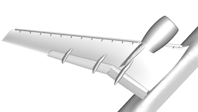
The benchmark problem is the well-known NASA high-lift Common Research Model (CRM-HL), which is shown in the following figure. It contains many difficult-to-mesh features such as narrow gaps and slat brackets. The Reynolds number based on the mean aerodynamic chord (MAC) is 5.49 million, which makes wall-resolved LES (WRLES) prohibitively expensive.
 |
| The geometry of the high lift Common Research Model |
University of Kansas (KU) participated in two TFGs: High Order Discretization and WMLES. We learned a lot during the productive discussions in both TFGs. Our workshop results demonstrated the potential of high-order LES in reducing the number of degrees of freedom (DOFs) but also contained some inconsistency in the surface oil-flow prediction. After the workshop, we continued to refine the WMLES methodology. With the addition of an explicit subgrid-scale (SGS) model, the wall-adapting local eddy-viscosity (WALE) model, and the use of an isotropic tetrahedral mesh produced by the Barcelona Supercomputing Center, we obtained very good results in comparison to the experimental data.
At the angle of attack of 19.57 degrees (free-air), the computed surface oil flows agree well with the experiment with a 4th-order method using a mesh of 2 million isotropic tetrahedral elements (for a total of 42 million DOFs/equation), as shown in the following figures. The pizza-slice-like separations and the critical points on the engine nacelle are captured well. Almost all computations produced a separation bubble on top of the nacelle, which was not observed in the experiment. This difference may be caused by a wire near the tip of the nacelle used to trip the flow in the experiment. The computed lift coefficient is within 2.5% of the experimental value. A movie is shown here.
 |
| Comparison of surface oil flows between computation and experiment |
 |
| Comparison of surface oil flows between computation and experiment |
- Since we obtain wall model data from the 2nd element away from the wall, it is important that isotropic elements be used near solid walls to ensure that turbulent eddies are resolved well there. That's why we prefer tetrahedral elements for complex geometries since one can always generate isotropic elements. In other words, inviscid meshes are preferred for WMLES!
- For very under-resolved turbulent flow, the use of an explicit SGS model such as WALE produces more accurate and robust results than a shock-capturing limiter. It is quite difficult to determine the appropriate amount of limiting.
Hello, as a newbie to cryptocurrency trading, I lost a lot of money trying to navigate the market on my own, then in my search for a genuine and trusted trader/broker, i came across Trader Bernie Doran who guided and helped me retrieve my lost cryptocurrencies and I made so much profit up to the tune of $60,000. I made my first investment with $2,000 and got a ROI profit of $25,000 in less than 2 week. You can contact this expert trader Mr Bernie Doran via Gmail : BERNIEDORANSIGNALS@GMAIL.COM and be ready to share your own, tell him you were referred by me
ReplyDeleteAt the angle of attack of 19.57 degrees (free-air), the computed surface oil flows agree well with the experiment with a 4th-order method using a mesh of 2 million isotropic tetrahedral elements (for a total of 42 million DOFs/equation), as shown in the following figures. The pizza-slice-like separations and the critical points on the engine nacelle are captured well. Almost all computations produced a separation bubble on top of the nacelle, which was not observed in the experiment. This difference may be caused by a wire near the tip of the nacelle used to trip the flow in the experiment. The computed lift coefficient is within 2.5% of the experimental value. A movie is shown here.